Classification and characteristics of rigid couplings
Fixed Rigid Couplings:
I: Rigid fixed – sleeve coupling
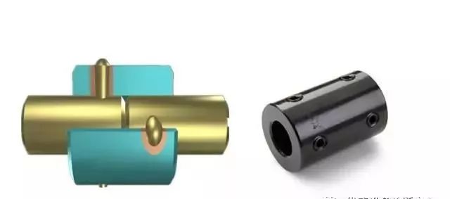
1. Composition: sleeve + connecting parts (key or pin transfer torque), sleeve material: 35 or 45 steel.
2. Features: simple structure, small radial size, low cost.
3. Application: the load is not large, the work is stable, the two axes are strictly in the center, widely used in the machine tool industry.
II: Rigid fixed – flange coupling
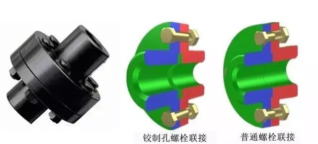
1. Composition: two semi-couplings with flanges, mounted separately at two shaft ends, to transfer torque by bolt connection.
2. Principle: Hinged hole bolt connection — by the bolt extrusion and shear transfer torque; Normal bolted connection – torque is transferred by friction on the flange joint surface.
3. Material: HT200 — used for torque below medium, V ≤35m/s; Zg270-500 or 35 steel — for heavy duty, V high applications.
4. Features: simple structure, reliable alignment, large transfer torque, but no vibration.
5. Application: low speed, large shaft rigidity, stable load, two shafts strictly in the middle, no impact occasions.
Conclusion:
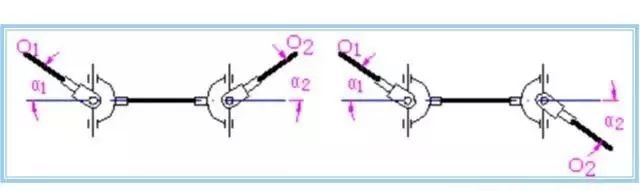
For rigid fixed coupling, due to manufacturing and installation errors, shaft deformation and temperature changes, the two shafts can not be strictly aligned, but there are different degrees of deviation or deflection. If the rigid coupling will cause additional dynamic load, the coupling or clutch structure is required to adapt to various forms of deviation, in order to ensure normal work.
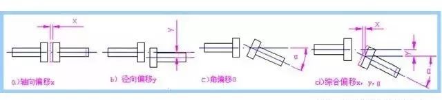
offset form of two axes
Movable Rigid Couplings:
I: Rigid movable – oldham coupling
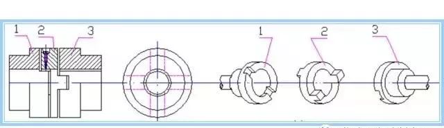
coupling construction
1. Composition: two end face open groove semi-coupling + a floating disk with convex teeth (tenon) on both sides, convex teeth can slide in the groove, so it can compensate the installation and operation of the relative displacement between the two shafts.
2. Features: floating disk center movement track for a circle, its diameter is equal to the eccentricity of the two axes E =△ Y, in the case of relative displacement of the two axes, the middle disk will produce a great centrifugal force, thus increasing the dynamic load and wear. Therefore, attention should be paid to the working speed shall not be greater than the specified value.
3. Material: two half coupling — 45 steel or ZG310-570 (for large size); Middle floating disk – 45 steel, hardened surface.
4. Application: radial offset △ Y large, T large, no impact, low speed transmission of two axis connection. Allowable Nmax =100~250r/min, △y≤0.04d, △α≤30 ‘.
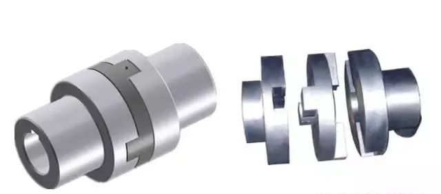
II: Rigid movable type – gear coupling

1. Composition: two semi-couplings with outer gear (1) + two shells with inner teeth (3) + connecting bolt (5), which transfer torque through meshing of inner and outer teeth.
2. Features:
Gear shape is involute, α = 20°, Z=30~80;
(2) Outer gear are apical ellipsoid, and the appropriate apical clearance and lateral clearance after meshing with the inner teeth allow a large comprehensive deviation;
Oil is stored in the housing to lubricate the meshing gear;
(4) due to meshing transmission, transfer torque is large;
(5) Manufacturing difficulties, high cost.
3. Material: 45 forged or cast steel, HB≥250; The shell HB 290 or higher.
4. Application: heavy machinery, allowing △ Y = 2.4~6.3mm, △α < 3°. Due to the difficulty of calculation, generally according to the torque check standard, select the appropriate size.
III: Rigid movable – universal joint
1. Composition: two fork joints 1, 3 + middle cross shaft 2 + pin (in the cross shaft) — to form a movable connection.
2. Features:
① A large angular offset between the two axes is allowed, α Max =35° ~ 45°(but α↑η↓);
② The change of α in operation can also work, but the instantaneous transmission ratio changes, and ω1≠ω2;
③ Small radial size.
3 disadvantages: when the active shaft angular velocity ω1 is a constant, the driven shaft angular velocity ω3 in a certain range (ω1cosα≤ω3 ≤ω1/cosα) change, → cause additional dynamic load.
4. Material: alloy steel 40Cr, 20Cr, etc.
5. Application: machine tools, automobiles, construction machinery and other equipment.
Conclusion:
Common characteristics of the above various couplings:
1. Rigid parts, lack of buffering vibration absorption capacity.
2 parts with relative sliding, wear ↑ gap ↑, when the load, speed change, cause impact.
3. Friction resistance between parts increases with the increase of load. When the resistance reaches a certain degree, it is difficult for parts to move → additional dynamic load.
The friction surface of this kind of coupling is required to be high hardness, and lubrication is required to reduce friction resistance.